Die Casting And Cnc Machining Of Hand-Cranked Generator Housing
| The casing is an important structural part of the hand-cranked generator, suitable for high-productivity die-casting production, and the castings formed by the center gate feeding method are dense. For the casing castings with irregular shapes and machining allowances left in the two bearing chambers and stop ports, the turning processing method can meet the precision matching requirements of the left casing and the right casing inner and outer stops, the bearing and the bearing chamber. |
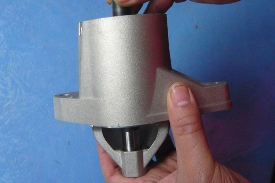
In the absence of a power supply, as a small-power, miniaturized emergency power supply device, a portable hand-cranked emergency power supply for power generation (or charging) has the characteristics of being fixed and reliable, easy to carry, flexible and light in operation [1,2]. The cast aluminum alloy casing with a base figure-eight double bearing chamber is an important part of a dual-handle portable hand-cranked generator. The casing consists of two parts: left and right.
In order to ensure the accuracy of assembly, the size of the casting product must strictly meet the requirements of the drawing.
Mould structure
The die-casting process has the characteristics of high efficiency, high yield, and less cutting processing. The die-casting mold used to produce the left and right housings uses one mold with two cavities. In view of the narrow and long casing itself, if the side gate bottom is used for feeding, even if the top of the casing can be filled, shrinkage or even cracking will still occur. In addition, it is more difficult to remove the gate waste along the outer contour, so choose the center gate , Its advantages are:
- ① Under the action of the diversion cone 19, the aluminum alloy liquid diffuses along 360°, with strong filling force, low resistance, and good casting appearance quality [4];
- ②The gate is cut by turning process, the cut surface is smooth and beautiful, and the work efficiency is high. Adopt the design
The full push rod ejection mechanism placed in the inner edge bearing chamber and close to the outer edge avoids the secondary ejection mechanism that must be used by the pusher plate mechanism [4]; It is drilled with a drilling machine, so that the mold does not have a core-pulling mechanism, and the casing casting is improved in the lathe fixture (a) left casing (b) die-casting mold structure (c) right casing
- 1. Movable bottom plate
- 2. Cushion
- 3. Push plate
- 4, 9, 14, 27. Fastening screw
- 5. Push rod fixing plate
- 6. Putter
- 7. Hexagon nut
- 8. Gasket
- 10. Fixed mold cavity plate
- 11, 22. Bushing
- 12. Fixed template
- 13, 23. Guide post
- 15. Hand crank shaft bearing chamber core
- 16. Movable core
- 17. Bearing chamber push rod
- 18. Mounting hole core
- 19. Shunt cone
- 20. Sprue bush
- 21. Fixed cavity
- 24. Reset lever
- 25. Movable core fixing plate
- 26. Movable mold cover
- 28. Push plate guide pin
- 29. The positioning accuracy of the push plate guide sleeve.
It can be seen from Figure 1 that the housing parts are in a figure eight shape. It can be seen from Figure 2 that if the fixed end on the left side of the movable mold core 16 is designed into a traditional step shape, the milling cutter will process an 81mm long core due to insufficient rigidity, resulting in a taper that makes the size out of tolerance and cannot be assembled. Figure 3 shows the structure of the moving model core, which can be processed by wire cutting, and is fastened with 4-M6 tail screws (14) to overcome the above drawbacks. Setting the casing 4-4.5 mounting hole core 18 in the fixed mold not only improves the density of the moving mold to accommodate too many cores, but also because the ejection direction of the mold is the same as the ejection direction of the casting, it is helpful For the smooth launch of castings.
1.3 The working principle of mould
The J1113B horizontal die-casting machine is used for die-casting in the cold press chamber, and it enters the spiral groove sprue sleeve 20 under the advancement of the injection punch, and then the aluminum alloy is sequentially pressed into the fixed mold cavity 21 along 360° under the action of the shunt cone, and then pressurized. After cooling, the mold is opened. Under the reaction of the three 7° chute on the inner wall of the sprue sleeve, the remaining material in the sprue sleeve and the casting tightly packed on the movable mold core 16 will perform a counter force, resulting in the weakest strength of the casing casting The inner gate 8 mm is broken, and the parting surface Ⅰ-Ⅰ is opened first; continue to open the mold, the parting surface Ⅱ-Ⅱ is opened, relying on the packing force of the movable mold core 16, 4- 4.5 mm The core is separated from the casing casting, the die-casting machine is started to eject the cylinder, and the 14 push rods can smoothly push out the casting and take it out.
In particular, the key to making good use of the center gate is how to use the simplest mechanism to ensure that the remaining material in the pressure chamber and the sprue break smoothly at the inner gate after the mold is opened. Among them, the spiral groove is used in the breaking mechanism. The sprue bushing is the cheapest and simplest, and the determination of the spiral angle and the depth of the spiral groove has a great influence.
1.4 Analysis of characteristics
The left and right casings use the same set of molds, and the left casing is turned into the right casing in the subsequent turning process, thereby saving a set of die-casting molds; the 2-4.5mm installation hole at the bottom of the casing is adopted The drilling fixture is drilled out, which not only avoids the complicated core pulling mechanism of the mold, but also improves the positioning accuracy of the casing casting in the car fixture; the core of the bearing chamber (that is, the shunt cone 19) has been chamfered at the head of the bearing chamber by 45° , Eliminates the chamfering process when turning the bearing chamber of the housing die-casting part.
2 Analysis of the structure and characteristics of the casing casting drill and car fixture In order to make the accuracy of the casting bearing chamber and the stop meet the drawing requirements and ensure that the left and right casings can be assembled smoothly after the bearings and the upper and lower shafts are installed in the left and right casings, the casing castings must be These key parts of the machine are cut and finished.
2.1 Analysis of the structure of the drilling machine fixture for the mounting hole of the chassis base frame Figure 5 shows the corresponding drilling machine fixture, which takes advantage of the good size consistency of the die-casting parts, and uses the two-circle adjacent part of the figure eight shape in the middle of the chassis as positioning ( The positioning cavity of the drill template 4 is cut out by wire cutting, and is assigned to the corresponding part of the casing casting 5, with a gap of 0.08 mm). The drilling machine fixture adopts the shell shape of two 68mm eccentric circles adjacent to the circumferential surface to form a clearance fit with the corresponding part of the drill template. This positioning method is equivalent to the positioning of two pins on one side, and the only one remaining axial degree of freedom is fingered Pinch to eliminate. This positioning and clamping method is widely used in the processing of small drilling parts.
- 1. Baffle
- 2. Fastening screw
- 3. Drill sleeve
- 4. Drill template
- 5. Chassis casting
2.2 The structure analysis and working principle of the fixture of the chassis lathe
2.2.1 Machinability analysis of housing parts
In order to remove the casting gate and increase the accuracy of the two bearing chambers and one stop of the housing die-casting part (with the accuracy of IT10) to IT7, leave a turning allowance of 0.5mm at the two bearing chambers and the stop, and pass The machining method of turning or milling achieves this accuracy, but because the two bearing chamber holes of the end cover are eccentric holes, the machining must be completed with the help of a set of machine tool fixtures. Based on the principles followed by the fixture design, it should be ensured that as many processing elements as possible are completed at one time. If you consider completing the above operations on the machining center, in order to complete the center gate taper shank removal on the back of the casing, two sets of milling fixtures must be used, and the operation is inconvenient.
2.2.2 Analysis of the structure and working principle of the lathe fixture
Figure 6 shows the fixture for the chassis lathe. The upper half of the housing is located at the center of the lathe spindle as the initial position for turning. The housing uses the 2-4.5mm hole on the base of the housing and two pins on one side are positioned on the A side of the fixture body 5 (see Figure 7); push to tighten The handle of the quick clamp 1 on the large plane of the clamp matrix 5 to the vertical position, at this time, it is connected to the compression block 6 of the lower pressing rod of the quick clamp 1.
Press the 68 mm arc surface on the parts of the casing, so that the degree of freedom of the parts of the casing is limited; The outer stop of 64mm of the shell (if it is the right housing, first flatten the outer stop and then use the blind hole boring tool to turn out the inner stop according to the figure).
- 1. Quick Fixture
- 2. Flange
- 3. Rectangular limit block
- 4. Fastening screw
- 5. Fixture matrix
- 6. Compression block
- 7. Locating pin
- 8. Clamp screw
- 9. Washer, hexagon socket head screw
- 10. Chassis casting
- 11. Cylindrical pin
- 12. Diamond pin
First, pull out the positioning pin 7 that is in clearance fit with the clamp body 5 and flange plate 2, turn the flange plate 2 (see Figure 8) to the vertical downward position of the handle of the quick clamp 1, and loosen it (2~3 teeth) Two cylindrical head hexagon socket screws 9, under the action of gravity, the fixture body 5 relies on the T-shaped sliding block on the back to slide along the T-slot of the flange 2 until it meets the edge of the flange 2 tightly.
Rectangular limit block 3 (see the E surface in Fig. 8, which acts as a limit), the fixture body slides into place. At this time, the axis of the bearing hole of the lower half of the housing coincides with the center of the lathe spindle, and the positioning pin 7 is inserted in place and tightened. Two cylindrical head hexagon socket screws 9; start the lathe to drill through the lower hole with a 18mm twist drill 3. The taper shank of the center gate will automatically fall off (but there are flash residues on the edge); call the boring tool 1 for coarse and fine Boring to 20+0.0150mm; call the inner groove cutter 4 to pass through the 20+0.0150mm hole (do not touch the wall) so that the tip of the tool is flush with the left end of the casing, and the tool is retracted horizontally by 2mm to facilitate the removal of residual flash at the gate.
Turn the flange 2 to the vertical up position of the handle of the quick clamp 1, pull the handle of the quick clamp 1 to the bottom, and the pressing block 6 will be separated from the casing for about 20mm, and pull out from the 2-4.5mm pin upwards. For the turned case, install the new case to be turned in the same way, and push the handle of the quick clamp 1 to the vertical upward position to lock the case; for the same reason, you can drill and turn the half shaft first
Hole and cut off the remaining flash of the gate, after parking, turn the flange 2 to the vertical up position of the handle of the quick clamp 1, pull out the positioning pin 7, and loosen the two cylindrical head hexagon socket screws (2 to 3 teeth) 9 Under the action of gravity, the fixture body 5 slides down along the T-shaped groove of the flange plate 2 by relying on the T-shaped slider on the back until the B surface is attached to the D surface of the flange plate 2. The axis of the half of the bearing hole coincides with the center of the lathe spindle, insert the positioning pin 7 in situ and tighten the two cylindrical head hexagon socket screws 9; start the lathe to repeat the above cycle.
2.3 Analysis of characteristics
Adopting one-side two-pin positioning, quick clamp clamping, T-slot sliding adjustment of eccentricity, rigid limit of the car clamp has high precision and easy operation, which expands the traditional thinking of eccentric parts finishing, and provides a stable and reliable switch during multi-hole machining. A new method with limit. The mounting hole of the chassis base 2-4.5mm is drilled with a drilling jig, which has good consistency and has the basic conditions for one-side two-pin positioning [5]. I chose ready-made, low-priced and fully-specified quick clamps
(GH-36060), under the premise of satisfying the functional requirements of the fixture, greatly simplified
The design and manufacturing links have been completed [6]. Turning out the right housing with the left housing die casting not only saves a set of die-casting molds and a set of vehicle fixtures, but also improves production efficiency.
For die-casting production, in order to improve the accuracy that must be achieved in the assembly of the whole machine, it is important to focus on the subsequent processing of die-casting parts, especially to improve the dimensional accuracy of some key elements. Therefore, it is important to use machine tool fixtures ingeniously and reasonably. An effective method can be regarded as the most economical and quickest process plan.
Link to this article: Die Casting And Cnc Machining Of Hand-Cranked Generator Housing
Reprint Statement: If there are no special instructions, all articles on this site are original. Please indicate the source for reprinting:https://www.cncmachiningptj.com/,thanks!
 PTJ® provides a full range of Custom Precision cnc machining china services.ISO 9001:2015 &AS-9100 certified. 3, 4 and 5-axis rapid precision CNC machining services including milling, turning to customer specifications,Capable of metal & plastic machined parts with +/-0.005 mm tolerance.Secondary services include CNC and conventional grinding, drilling,die casting,sheet metal and stamping.Providing prototypes, full production runs, technical support and full inspection.Serves the automotive, aerospace, mold&fixture,led lighting,medical,bicycle, and consumer electronics industries. On-time delivery.Tell us a little about your project’s budget and expected delivery time. We will strategize with you to provide the most cost-effective services to help you reach your target,Welcome to Contact us ( [email protected] ) directly for your new project.
Link to this article:Die Casting And Cnc Machining Of Hand-Cranked Generator Housing
Reprint Statement: If there are no special instructions, all articles on this site are original. Please indicate the source for reprinting.:ODM Wiki,thanks!^^